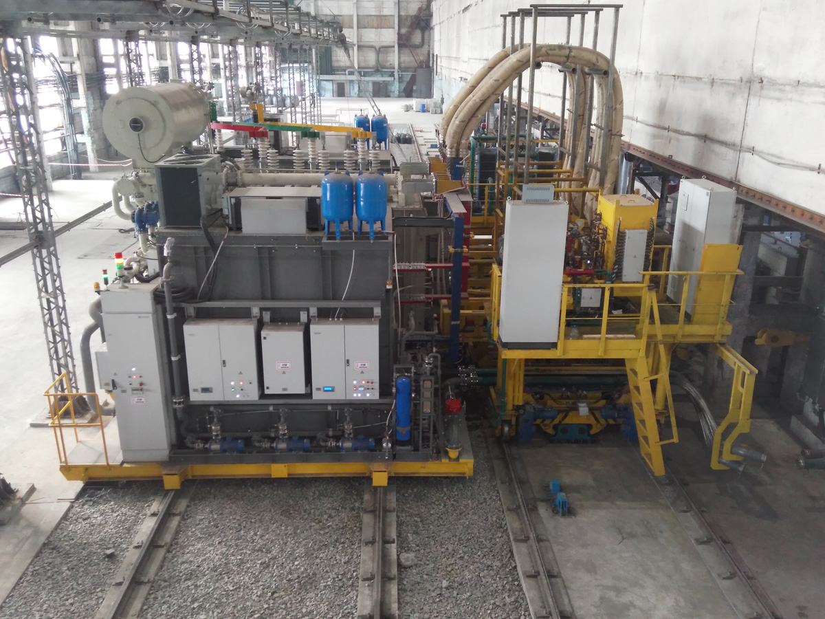
POWERFUL SILICON-CONTROLLED PORTABLE RECTIFIER
for direct graphitation furnaces
Grahitized electrode generation includes a number of operations related to a heat treatment of carbon products. The direct heating graphitization furnaces (DGF) or Castner furnaces have become widespread in the industry. Graphitization in the DGF can significantly reduce energy consumption and improve quality of electrodes. DGF is an electric resistance furnace, where carbon slabs acting as a structural element of the furnace and surrounded by a layer of thermal insulating carbon charge, represent an active electrical load resistance in the graphitization unit common circuit: electric energy source – metal busbars – furnace.
As a basic structural element of electric power source, a portable, fully controlled rectifier is chosen in view of the following considerations.
- No complex or technically challenging DC bussing is required for portable construction design.
- No need to use expensive disconnect switches for furnace DC circuits.
- Fully controlled (and smoothly adjustable) rectifier allows to ensure the highest technological requirements for the heat treatment of electrode slabs
Currently, the use of portable rectifiers for DGFs has become a worldwide trend. A general view of a designed and manufactured rectifier with a column compressor and DC cables connecting the rectifier to the furnace is displayed below.

The rectifier is implemented according to 12-pulse rectification circuit. Thyristor version of the rectifier, as compared with the diode version, has the following advantages:
- enable smooth adjustment of the output voltage from 0 to the rated value;
- deliver high-speed protection against short circuits through an impact on the thyristor control electrodes, which increases the reliability of the rectifier;
- allow to switch rotating rectifier and transformer on-load tap-changers with preliminary smooth decrease of current to 0, which increases their service life and reliability;
- allows to reduce significantly the individual characteristics decline over a period of time (in particular, saturable core reactors, which leads to electrical imbalance on the valve windings and, consequently, to a decrease in the rectifier current load).
The slight difference in cost of thyristors s compared to the cost of diodes makes them more preferable both by cost and by functional opportunities.
The rectifier voltage (current) control can be smooth over the entire range of load changes, but is not the best option from the point of view of energy performance and impact on the supply network. Therefore, as a primary option, the smoothly-stepped control is available, which consists in combining transformer on-load tap-changing with smooth regulation within a range of one or two steps.
The liquid cooling is applied in the product. Technical circulating water is used in the external circuit, and deionized water and oil are used in the internal circuit.
For reliable operation of the rectifier, the cooling systems are made redundant in both pumps and heat exchange elements.
A pantograph disconnector is used as a switching device with the portable rectifier 10kV network.
| № | Characteristic description | MU | Value |
| Rectifier |
|||
| 1 | Power supply voltage | V | 10 000 |
| 2 | Frequency | Hz | 50 |
| 3 | Tap changing method | OLTC | |
| 4 | Rated output voltage | V | 150 |
| 5 | Output voltage smooth control range | V | 0-150 |
| 6 | Rated output current | kA | 180 |
| 7 | Pulse equivalent rectifying circuit | 12 | |
| 8 | Number of backup thyristors on one arm | pc. | 1 |
| 9 | Noise emission at 1 m, max | dB (A) | 80 |
| 10 | Number of positioning drives | pc. | 4 |
| 11 | Rated voltage of positioning motor | V | 380 |
| 12 | Maximum (adjustable) positioning speed | m/min. | 6 |
| 13 | Dimensions | mm | 11673х6895х6345 |
| Harmonic filter |
|||
| 14 | Total installed capacity | kVAr | 8400 |
| 15 | Total generating capacity with rated voltage | kVAr | 6474 |
The conversion efficiency in the rated mode of operation (with rated input and output parameters) is at least 96.5%.
The power factor including the harmonic filter and with rectifier operating not on the extreme taps of OLTC is not lower than 0.97.
The rectifier is mounted on a mobile platform, self-propelled by the track. The following elements are disposed on the rectifier unit self-propelled platform (RUSP):
- converter transformer with cooling system;
- 2 containers with converter sections and cooling systems;
- DC busbar with cooling system;
- AC busbar;
- pantograph disconnector for switching with 10kV network;
- 2 remote controls for of RUSP propelling;
- auxiliary voltage distribution cabinet;
- pipes for the distribution of circulating water;
- control cabinets for the rectifier, self-propelled platform and RUSP propelling;
- direct current gauges;
- trays for secondary circuits wires.
The rectifier has been in successful operation at the electrode plant since October 2017.
