Asynchronous valve cascade (hereinafter the AVC) is designed to control the start-up and adjust the speed of a wound-rotor induction motor.
Application of AVC within the drive provides for the following modes of operation:
- start from zero to a given rotation speed with restricted in-rush starting current;
- drive’s motoring mode with regeneration of slip current to the supply network;
- stepless speed control;
- holding of rotation speed on a set level with an accuracy of at least 1%;
- local / remote control modes;
- restriction of the motor current build-up rate to limit dynamic loads in the mechanism;
- detection, identification and prevention of further development of emergency processes in AVC, engine and related equipment;
- diagnostics, continuous monitoring, and indication of parameters describing the electric drive performance;
- indication of output parameters in real time with recording the time when emergency mode occured.
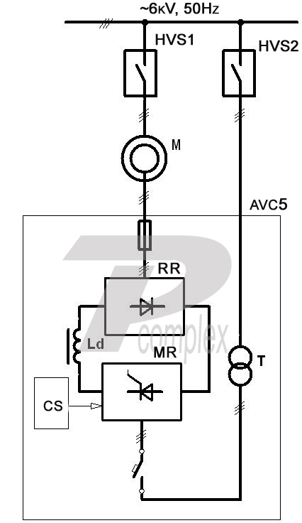
The AVC consists of:
- rotary uncontrolled rectifier (RR);
- smoothing reactor (Ld);
- mains controlled rectifier (MR);
- matching network transformer (T);
- control systems (CS).
Operating principle
The principle of asynchronous motor speed control in AVC lies in incorporation into the rotor circuit of a back-EMF multiplier. Adjusting the value of emf multiplier makes it possible to regulate the rotor current, and hence the motor torque.
As a source of back-EMF in AVC a thyristor-controlled rectifier (MR) is used. The MR is connected to the supply mains and operates as a grid-controlled inverter.
The rotor’s slip energy is converted into DC energy by the rectifier (RR), and then inverted by MR into the AC energy of mains frequency. The speed control is carried out by adjusting the back-EMF through delay angle variation of thyristors RR.
Transformer T is designed to match output voltage of the rotor with the network voltage.
Energy saving in processing plants based on AVC electric drives can amount to 30% compared to the use of rotary (resistive) stations.
A combined cooling system is implemented in AVC. During low loads power bridges are cooled naturally by air. When the temperature rises above the controlled limit, the system turns on forced cooling. This system allows to minimize the equipment’s maintenance during operation under severe contamination condition.
Control System (CS)
The CS provides the user with a number of service opportunities:
- quick access to all adjustable parameters. The parameters are displayed in numerical decimal format on the console terminal screen,
- displaying a message re. the cause of malfunction, if any, on the console terminal screen via embedded self-diagnostic program,
- specified indication of triggered protections. When a protection is activated, a message is displayed in a text form on the console terminal with respect to the first activated protection followed by all subsequent types;
- automatic recording of an emergency “track” via a specific built-in software for recording of given parameters to a file, with possible further handling of this data on a PC.
Protection system
AVC ensures the following types of protection and blocking:
- external and internal faults;
- protection against unacceptable by value and duration overload currents of power circuit elements and powered electric motors (time-current protection);
- cooling system malfunction protection;
- power system overvoltage and undervoltage protection;
- motor overspeed protection;
- power sources failures protection;
- interlock against turn-on with alarming and warning signals