
UPTF5 provides for:
- a start from zero to the rated rotary speed for a given amount of time set by intensity controller with a restricted starting current;
- maintaining a constant dynamic torque during the entire start process;
- conveyor start-up without belt slippages and jerks;
- underspeed start-up and run with 25% of the nominal torque;
- preset diagrams of velocity, dynamic forces and accelerations;
- unacceptable engine overloads protection.
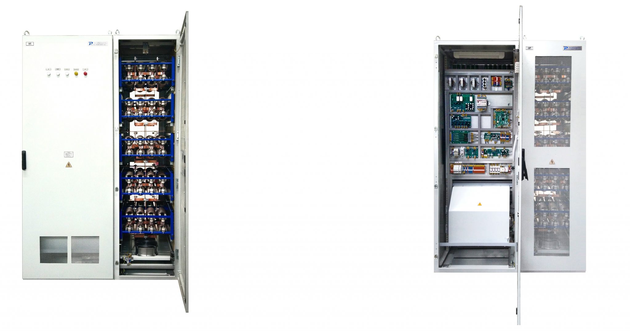
Basic specifications
UPTF5 is produced with voltage of up to 1600V and current of up to 630A.
It is possible to implement any object orientation of UPTF5 at the request of the Customer

Speed-torque characteristic of UPTF5 four-stage resistor starter
Operating principle
Adjustment of engine acceleration rate is made via rotor current regulation by a silicon-controlled bridge and contactless connection of resistor stages (please refer to the graph).
The power part of the UPTF5 consists of a rectifier bridge, switching thyristors, ballast resistors and a contactor.
The AC inputs of the rectifier H-bridge are connected to the rotor. Four stages of series ballast resistors are connected to the bridge output. Three switching thyristors shunt three stages of ballast resistors The contactor is connected to the rotor circuit and shunts it at the end point of motor acceleration. The number of stages can vary and depends on the motor shunt characteristic.

UPTF5 functional diagram
The UPTF functional diagram is shown in Figure and has the following functional blocks:
- linear intensity controller (IC),
- rotor EMF controller (PI controller);
- current controller (I controller) in the IC limiting circuit;
- I-limitations – setpoint in the IC limiting circuit;
- rectifier pulse-phase control circuit (PPCC);
- voltage sensors (VS);
- current sensors (CS);
- phase shift equalizer (PE), that compensates synchronizing voltage phase shift from analog filter;
- EMF release unit (hardware unit);
- EMF normalization unit (NU);
- speed calculation unit (w(f));
- stage switching unit (SS).
All Control System tasks are performed by software/hardware method. The CS output signals are:
- thyristor rectifier control pulses;
- control pulses of switching thyristors changing stages;
- a circuit breaker trip signal;
- indication of operating modes;
- text messages on the console terminal regarding operating modes and causes of emergency shutdowns;
- CAN communication.
Protection system
UPTF5 provides the following types of protection:
- overcurrent protection;
- оnetwork and switching overvoltage protection;
- overload protection in accordance with the name plate, time-current characteristic of motor g tolerance;
- power circuit disconnection protection;
- open-phase switching-on protection;
- extended start protection;
- protection against failure of control system power sources;
- protection against outage or unacceptable drop in station auxiliaries voltage.