The VTE (P) series excitors feature static, thyristor, high-speed excitation systems (hereinafter the ES)
General characteristics of ES series:
- covered range of motor rated power:
-up to 27500 kW; - types of motor excitation:
-brush;
-brushless; - range of rated current and excitation voltage:
-excitation current: up to 1000 A;
-excitation voltage: up to 230 V; - supported synchronous motors starting modes:
-direct-on-line start;
-inductor easy and heavy start;
-with a soft starter;
-with a frequency converter (ES control over the “4-20mA” channel); - rectification circuit:
-three-phase Grets bridge;
-three-phase single-way;
-one-group and two-group circuits;
-IGBT for brushless ES; - transformer availability:
-with a transformer;
-without a transformer (using the Customer’s transformer); - redundancy circuit:
-hot standby according to «1+1» arrangement: dual-channel full redundancy of converters and Automatic Excitation Controls;
-cold standby with distributing cabinet:
-two ES for one motor;
-one ES for two motors;
-no reserve; - power converter cooling:
-natural air cooling – self-cooled thyristor excitors (VTE) up to 400A;
-forced air cooling – forced air-cooled thyristor excitors (VTP) above 400A;
-combined cooling; - excitation controller:
-automated controller (5 types);
-manual controller; - network interfaces for communication with Automated Process Control System:
-Profibus DP, Modbus RTU, Ethernet, CAN, etc. - commissioning time: 4 hours.
Basic technical specifications
ES functions:
- motor starting techniques:
-direct motor starting with excitation application to a starter current function and to a slip function;
-inductor heavy start with excitation application upon bypass switch closing;
-inductor easy start with excitation application at the reactor starting stage before bypass switch closing;
-start with a frequency converter and with excitation current mode control by “4-20mA” channel from the frequency converter;
-start with a soft starter;
-cut into mains by precision synchronization method in the motor’s generator cycle with an auxiliary drive; - manual, automatic and shock automatic operation modes;
- manual control parameters:
– excitation current; - automatic adjustment of one of the following parameters:
-reactive engine power – for associated equipment reactive power compensation provided that the level thereof is relatively constant;
-motor voltage – for voltage regulation of the motor supplying network;
-COS (φ) engine – for stability improvement of engines with variable load;
-reactive power in a remote load bus – for reactive power compensation in the site, shop, substation input when its level is variable; - transfer during control mode changing:
-a bumpless transfer;
-transfer to a setpoint. - regulation in a shock automatic mode:
-interload time – regulation of the main parameter in the selected automatic mode;
-at the commencement of load – forcing the excitation with a given level in order to increase the stability of abruptly variable load motors; - excitor’s check before start:
-auto check of the input power voltage phase sequence;
-starting resistance circuit continuity check;
-current check of the excitor and excitation circuit;
-rotor circuit insulation resistance check with indication of the present resistance; - control accuracy:
-motor voltage – 0.2%;
-motor reactive power – 0.5%;
-Cos(φ) engine – 0.5%;
-excitation current in the manual mode – 0.5% - rotor electromechanical oscillations’ damping, ensuring motor’s static and dynamic stability;
- motor’s full and reactive current droop (compounding);
- excitation forcing;
- dynamic (electric) braking mode;
- re-synchronization mode in the Automatic Transfer Switch and Automatic Circuit Recloser modes for the motor’s power supply;
- indication of consumed active energy, consumed inductive and capacitive reactive energy from the motor’s start-up till its shutdown, as well as for the ES entire operation;
- enter-a-password function in order to change the parameter;
Control system
All CS tasks are fulfilled by a software and hardware approach.
- the control structure of the Automatic Excitation Control – “ARV-SD (stabilizing)” with the following control channels (see figure):
-PI(D)-controller:
-by deviation of the main controlled variable – proportional-integral section;
-by the motor voltage derivative (for the motor voltage regulation mode) – differential section;
-system stabilizer (PSS, for the motor voltage regulation mode):
-by the excitation current derivative – If`;
-by the motor frequency derivative – Fs`;
-by the motor frequency deviation – dFs.
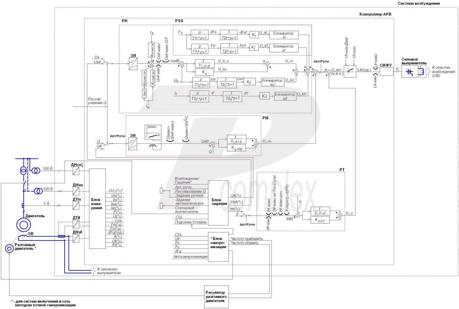
Control system structure
Automatic excitation control limiters
- minimum and maximum motor voltage;
- minimum and maximum excitation current;
- maximum excitation current with no conductivity in any converter arm;
- “P/Q” – minimum under-excitation limitation – limitation of motor reactive power subject to the active power;
- stator overcurrent limiter by time-dependent characteristic;
- rotor overcurrent limiter by time-dependent characteristic;
- super-excitation duration by the time-dependent overload characteristic of the rotor;
Protection system
- against internal short circuits in the converter;
- against external short circuits on the DC side;
- loss of excitation protection;
- a long drawn start protection;
- asynchronous run protection;
- overvoltage in the rotor;
- protection against the stator circuit breaker a-contacts malfunction and control duplication thereof on the stator current;
- motor standstill protection (presence of excitation on the stopped motor – in case of its stator circuit breaker a-contacts malfunction);
- protection against voltage transformer feedback circuit disconnection:
-authorization to start when there is no feedback;
-automatic transfer to a manual mode when the feedback is disconnected; - protection against current transformer feedback circuit disconnection:
-inhibition of excitation application during start-up and feedback disconnection; - against forcing excessive duration limiter failure and excitation overcurrent limiter failure;
- against the “P/Q” minimum excitation limiter failure and transfer to a manual mode with set excitation that ensures over-excitation mode;
- against the conductivity loss on the the converter arm – continue the ES operation with current limitation;
- against brush rig and excitation circuit failures – control of the excitation circuit resistance: “cable – brush rig – rotor”;
- protection as per specified temperature of excitation winding;
- control of power circuit insulation resistance:
-control of excitation circuit and rectifier AC circuit
-indication of pole with minimum insulation resistance value;
-numeric indication of insulation resistance value in kΩ. - external protections: processing of signals such as “dry contact” from the Customer’s instrumentation gages (by vibration, oil lubrication, bearing temperature, etc.) with the possibility to generate both warning signals and an emergency shutdown.
Documentation
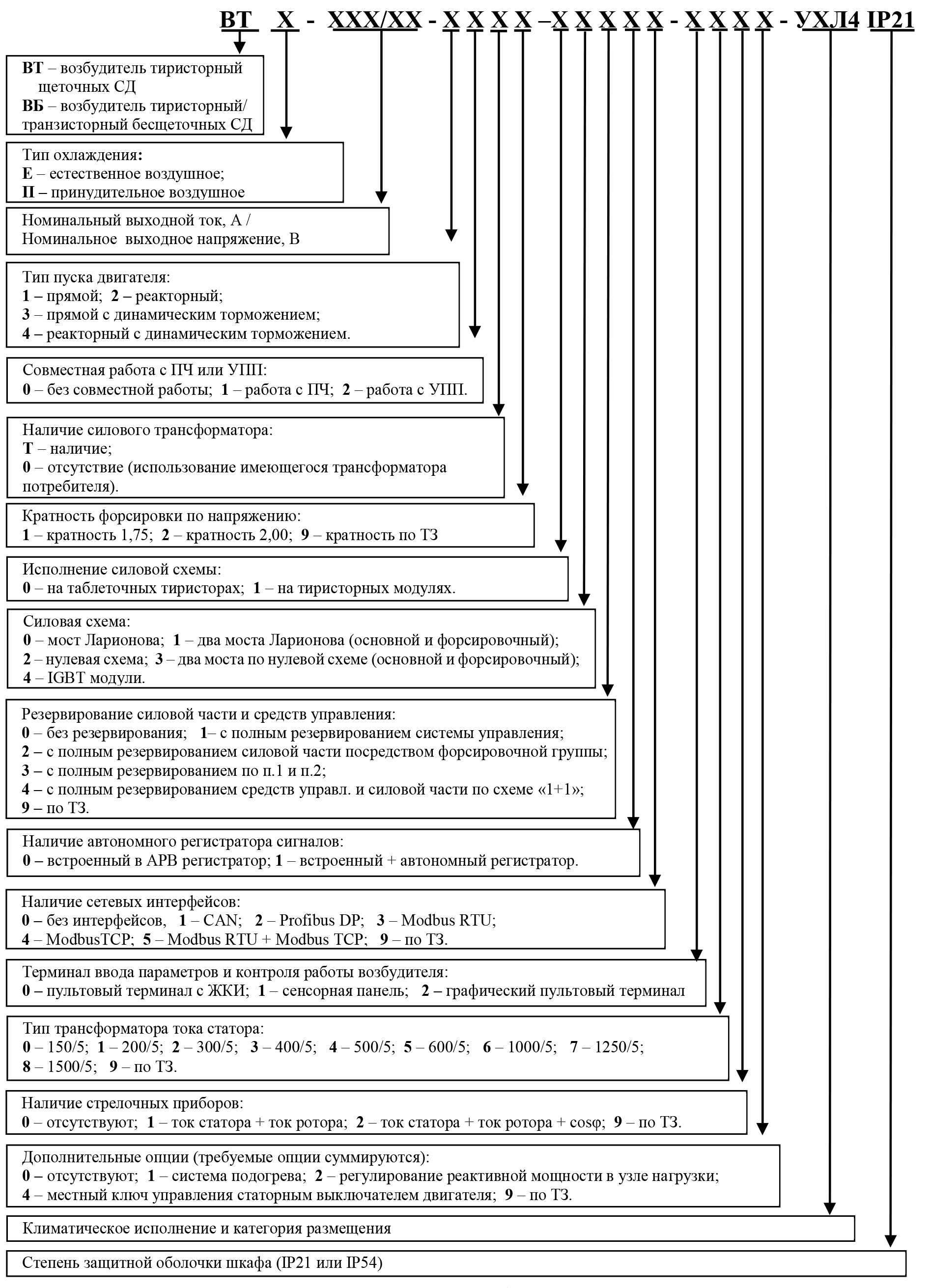
The structure of the symbol